Pipeline #
Never return. Push your data through a chain of processors.
Known as: Pipeline [DDS].
Variants:
By scheduling:
- Stream processing [DDIA] / Nearline system [DDIA],
- Batch processing [DDIA, DDS] / Offline system [DDIA].
Examples:
- Pipes and Filters [POSA1, POSA4, EIP] / Workflow System [DDS, DDIA],
- Choreographed (Broker Topology) Event-Driven Architecture (EDA) [SAP, FSA, DDS] / Event Collaboration [DEDS],
- Data Mesh [LDDD, SAHP],
- Function as a Service (FaaS) [DDS] / Nanoservices (pipelined).
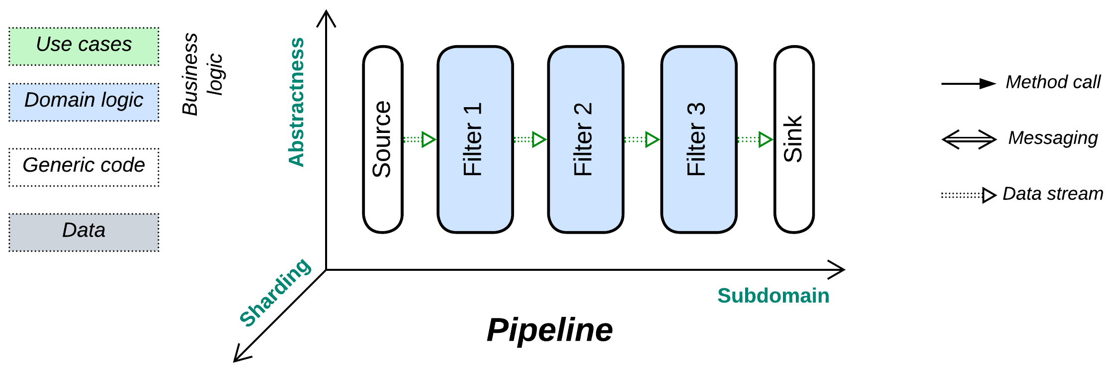
Structure: A component per step of data processing.
Type: Main.
| Benefits | Drawbacks |
|---|---|
| It is very easy to add or replace components | Becomes too complex when the number of scenarios grows |
| Multiple development teams and technologies | Poor latency |
| Good scalability | Significant communication overhead |
| The components can be reused | Error handling may be non-trivial |
| The components can be tested in isolation |
References: Pipes and Filters are defined in [POSA1] and are the foundation for part 3 (Derived Data) of [DDIA]. [DDS] has an overview of all kinds of Pipelines in general while [FSA] has a chapter on Event-Driven Architecture. [DEDS] is dedicated to Event-Driven Architecture. The [SAHP] chapter on Data Mesh was written by the pattern’s author. [EIP] is a whole book about distributed Pipelines.
Pipeline is a variation of Services with no user sessions [DDS], a unidirectional data flow, and often a single message type per communication channel (which thus becomes a data stream). As processed data does not return to the module that requested processing, there is no common concept of request ownership or high-level (integration, application) business logic, which is instead defined by the graph of connections between the components. On the one hand, as all the services involved are equal and know nothing about each other (their interfaces are often limited to a single entry point), it is very easy to reshape the overall algorithm. On the other hand, the system lacks the abstractness dimension, thus any new use case builds a separate pipeline which may easily turn the architecture into a mess of thousands of intrinsically interrelated pieces when the number of scenarios grows. Moreover, error handling requires dedicated pipelines that roll back changes to the system’s state which had been committed by earlier steps of a failed use case.
Performance #
Because any task for a pipeline is likely to involve all (or most of, if branched) its steps, there is no way to optimize away communication. Therefore, latency tends to be high. However, as pipeline components are often stateless, multiple instances of individual services or entire pipelines can run in parallel, making Pipeline a highly scalable architecture.
Another point to observe is that a local pipeline naturally spreads the load among the available CPU cores (by using one thread per component) without any explicit locks or thread synchronization.
Dependencies #
There are three ways to build communication in a pipeline, each with different dependencies:
- Commands make each service depend on the services it sends messages to. It is easy to add a new input to such a pipeline.
- With publish/subscribe each service depends on the services it subscribes to. That case favors downstream branching with multiple consumers.
- Services may share a message schema, in which case all of them depend on it, not on each other. That allows for reshuffling the services.
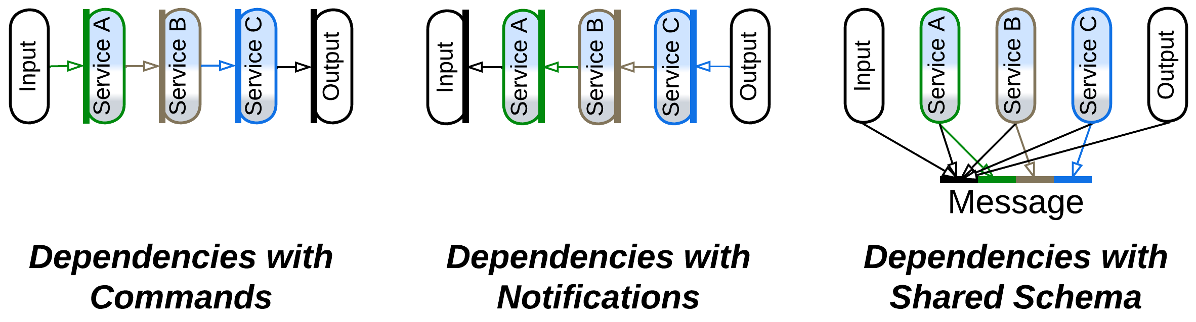
See the Choreography chapter for more detailed discussion.
Applicability #
Pipeline is good for:
- Experimental algorithms. This architecture allows for the data processing steps both to be tested in isolation and connected into complex systems without changing the existing code.
- Easy scaling. Pipelines tend to evenly saturate all the available CPU cores without any need for custom schedulers. Stateless services can run distributed, thus the Pipeline’s scalability is limited only by its data channels.
- Tailoring projects. Many pipeline components are abstract enough to be easily reused, greatly reducing the cost of serial development of customized projects once the company builds a collection of common reusable services.
Pipeline does not work for:
- High number of use cases. The number of components and their interactions is going to be roughly proportional to the number of supported use cases and will easily overwhelm any developer or architect if new scenarios are added over time.
- Complex use cases. Any conditional logic written as two or three lines of code with orchestration is likely to need a separate pipeline and dedicated services with choreography. Errors and corner cases are remarkably difficult to handle [FSA].
- Low latency. Every step of a data packet along its journey between services takes time, not in the least because of data serialization. Moreover, the next service in the chain may still be busy processing previous data packets or its activation involves the OS scheduler.
Relations #
Pipeline:
- Is a kind of Services with unidirectional communication and often a single input method.
- Is involved in CQRS, Polyglot Persistence with derived databases, and MVC.
- Can be extended with a Proxy, Middleware, or Shared Repository.
Variants by scheduling #
A pipeline may be either always active or just run once in a while:
Stream processing, Nearline system #
Stream processing [DDIA] is when the pipeline components (jobs, processors, filters, services – whatever you prefer to call them) are actively waiting for input and process each incoming item immediately. This results in near-real-time (nearline) latency [DDIA] but the pipeline will then always use resources, even when there is nothing for it to process.
Batch processing, Offline system #
Batch processing [DDIA, DDS] happens when a batch of input items is first collected into storage, and then the pipeline is run (often on a schedule) to process it. Such a mode of action is called offline [DDIA] as the processing results are delayed. However, the company saves on resources because the pipeline is only active for brief periods of time.
Examples #
Pipelines can be local or distributed, linear or branched (usually trees, but cycles may happen in practice), they may utilize a feedback engine to keep the throughput of all their components uniform by slowing down faster steps or scaling out slower ones. In some systems pipes (channels) or filters (services) persist data. Pipes may store the processed data in files or databases to enable error recovery and event sourcing. Filters may need to read or write to a database, which is often shared, if the data processing relies on the system’s state. Moreover, transferring data through a pipe may be implemented as anything ranging from a method call on the next filter to a pub/sub framework.
Such a variety of options enables the use of pipelines in a wide range of domains. Notwithstanding, there are a few mainstream types of Pipeline architectures:
Pipes and Filters, Workflow System #
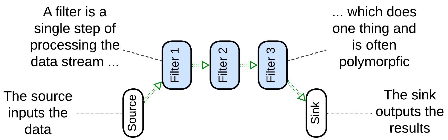
Pipes and Filters [POSA1, POSA4, EIP] usually name a linear local system which obtains data with its source, passes the data through a chain of filters, connected by pipes, and outputs it via a sink. The entire pipeline may run as a single process to avoid the overhead of data serialization. It may range from a Unix shell script which passes file contents through a series of utilities to a hardware pipeline for image processing in a video camera. The filters tend to be single-purpose (handle one type of payload) and stateless. In some cases a filter may use dedicated hardware (for encryption or audio/video processing). The entire pipeline often operates a single data format (Stamp Coupling [SAHP]).
Though most commonly a filter waits for data to appear in its input pipe, processes it, and pushes the result to its output pipe, thus allowing for multiple filters to run in parallel, some implementations may let the source push the data through the entire pipeline all the way to the sink, with each filter directly calling the next filter in the line or, alternatively, the sink can pull the data by making direct upstream calls [POSA1]. The last two approaches remove the need for pipes but are then limited to using a single CPU core.
Workflow [DDIA, DDS] is a more modern name for similar stepwise processing which often stores intermediate results in a file or database and may run distributed. However, the same word generally describes the sequence of high-level steps in a use case [PEAA], and is another name for application or integration logic.
Examples: Unix shell pipes, processing of video streams, many types of hardware.
Choreographed (Broker Topology) Event-Driven Architecture (EDA), Event Collaboration #
Event-Driven Architecture (EDA) means that the system is built of services which use events to communicate in a non-blocking way. The idea is similar to the actor model of telecom and embedded programming. Thus, EDA itself does not define anything about the structure of the system (except that it is not monolithic).
In practice, there are two kinds of Event-Driven Architectures:
- Choreographed / Broker Topology / Event Collaboration [DEDS] – the events are notifications (usually via publish/subscribe) and the services form tree-like structures, matching our definition of Pipeline.
- Orchestrated / Mediator Topology / Request-Response Collaboration – the events are request/confirmation pairs and usually there is a single entity that drives a use case by sending requests and receiving confirmations. Such a system corresponds to our Services metapattern with the supervisor being an Orchestrator, discussed in a separate chapter.
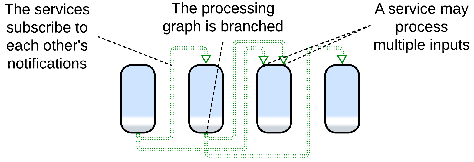
An ordinary Choreographed Event-Driven Architecture [SAP, FSA, DDS] is built as a set of subdomain services (similar to those of the parent Services metapattern). Each of the services subscribes to notifications from other services which it uses as action/data inputs and produces notifications that other services may rely on. For example, an email service may subscribe to error notifications from other services in the system to let the users know about troubles that occur while processing their orders. It will also subscribe to the user data service’s add/edit/delete notifications to keep its user contact database updated.
This example shows several differences from a typical Pipes and Filters implementation:
- The system supports multiple use cases (e.g. user registration and order processing).
- A service has several entry points (the email service involves an order error handler and user created handler).
- A notification that a service produces may have many subscribers or no subscribers (nobody needs to act on our sending an email to a user).
Those points translate to difference in structure: while Pipes and Filters is usually a linear chain of components, EDA entails multiple branched (and sometimes looped) event flow graphs over a single set of subdomain services.
Pipelined Event-Driven Architecture (often boosted with event sourcing) works well for highly loaded systems of moderate size, but larger projects are likely to grow prohibitively complex graphs of event flows and service dependencies. The architecture’s scalability is limited by the services’ databases and the pub/sub framework employed.
Event-Driven Architecture may involve a Gateway as a user-facing event source and sink and a Middleware for an application-wise pub/sub engine. Front Controller [SAHP] or Stamp Coupling [SAHP] are used if it is important to know the state of requests that are being processed by the pipeline.
Examples: high performance web services.
Data Mesh #
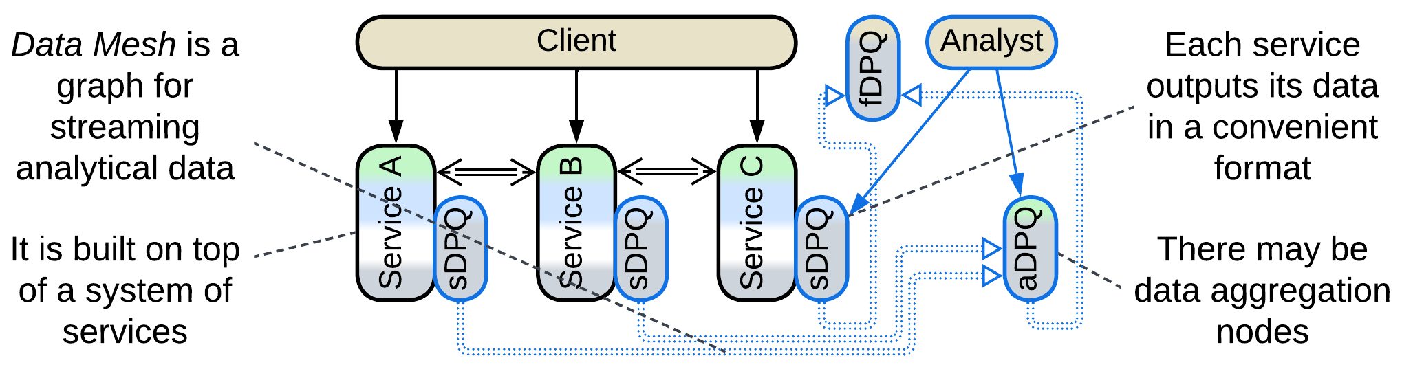
First and foremost, Data Mesh [LDDD, SAHP] is not a Mesh, but rather a Pipeline. This architecture applies CQRS on the system level: it separates the interfaces and channels through which the services change their state (matching commands or OLTP of CQRS) and the ones used to retrieve their data (similar to queries or OLAP). That results in two overlapping subsystems, operational and analytical, that share most of their nodes.
The operational system is an ordinary Microservices or Event-Driven Architecture.
The analytical system contains Data Product Quanta (DPQ) – services that provide convenient access (streaming, replaying, and possibly querying) to parts of the system’s data. The DPQs are assembled into a graph akin to Event-Driven Architecture. There are three kinds of DPQs [SAHP]:
- A source-aligned (native) DPQ (sDPQ) is coupled to an operational service and streams (or provides queries into) its data. It is likely to be implemented as a Reporting Database.
- An aggregate DPQ (aDPQ) merges and transforms inputs from several sources (sDPQs or other aDPQs). It is similar to a Query Service.
- A fit-for-purpose (custom-made) DPQ (fDPQ) is an end-user (leaf application) of the Data Mesh’s data. It may collect a dataset for machine learning or let a business analyst do their research. fDPQs tend to be short-lived one-off components.
There is a pragmatic option to allow an operational service to resort to the analytical system’s DPQs to query other services’ data instead of messaging them directly or implementing a CQRS View and subscribing it to events that flow in the operational system.
Function as a Service (FaaS), Nanoservices (pipelined) #
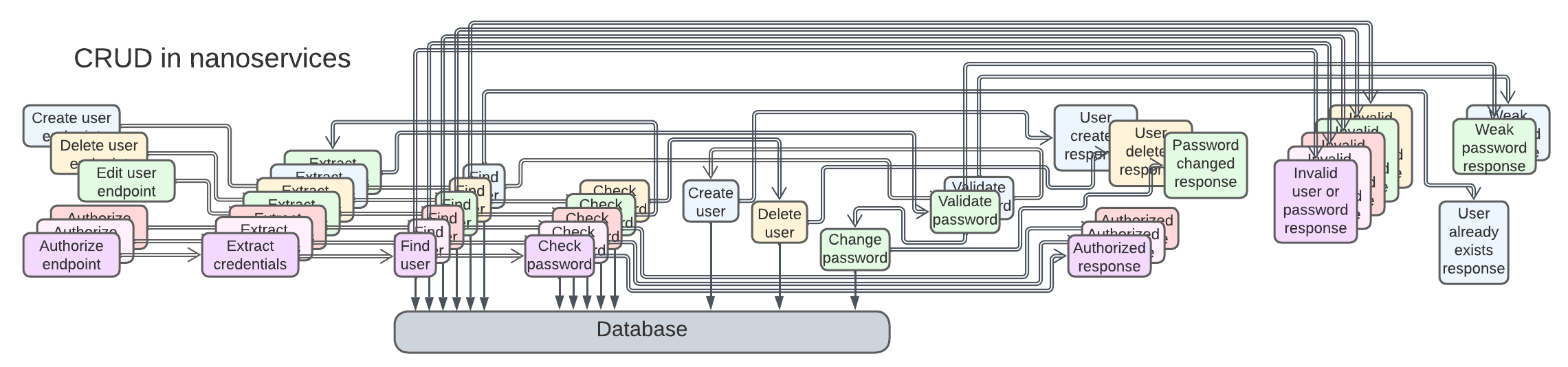
A nanoservice is, literally, a function as a service (FaaS) [DDS] – a stateless (thus perfectly scalable) component with a single input. They can run in proprietary cloud Middleware over a Shared Database and are chained into pipelines, one per use case. The code complexity stays low, but as the project grows, the integration will quickly turn into a nightmare of hundreds or thousands of interconnected services.
Nanoservices are good for rapid development of small elastic (dynamically scalable) applications. The supported load is limited by the Shared Database, and the project evolvability is limited by the complexity of scenarios. As any use case is going to involve many asynchronous steps, latency is not a strong side of Nanoservices.
Evolutions #
Pipeline inherits its set of evolutions from Services. Filters can be added, split in two, merged, or replaced. Many systems employ a Middleware (a pub/sub or pipeline framework), a Shared Repository (which may be a database or a file system), or Proxies.
There are a couple of pipeline-specific evolutions, with more details provided in Appendix E:
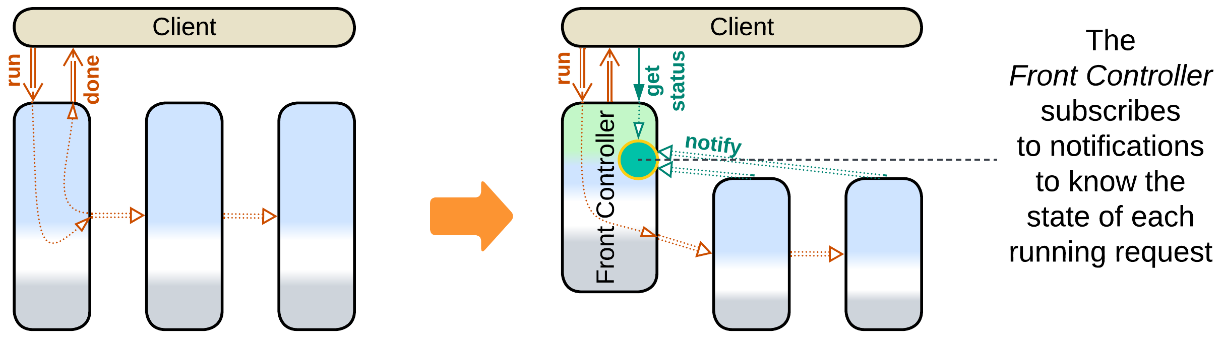
- The first service of the Pipeline can be promoted to a Front Controller [SAHP] which tracks the status updates for every request it handles.
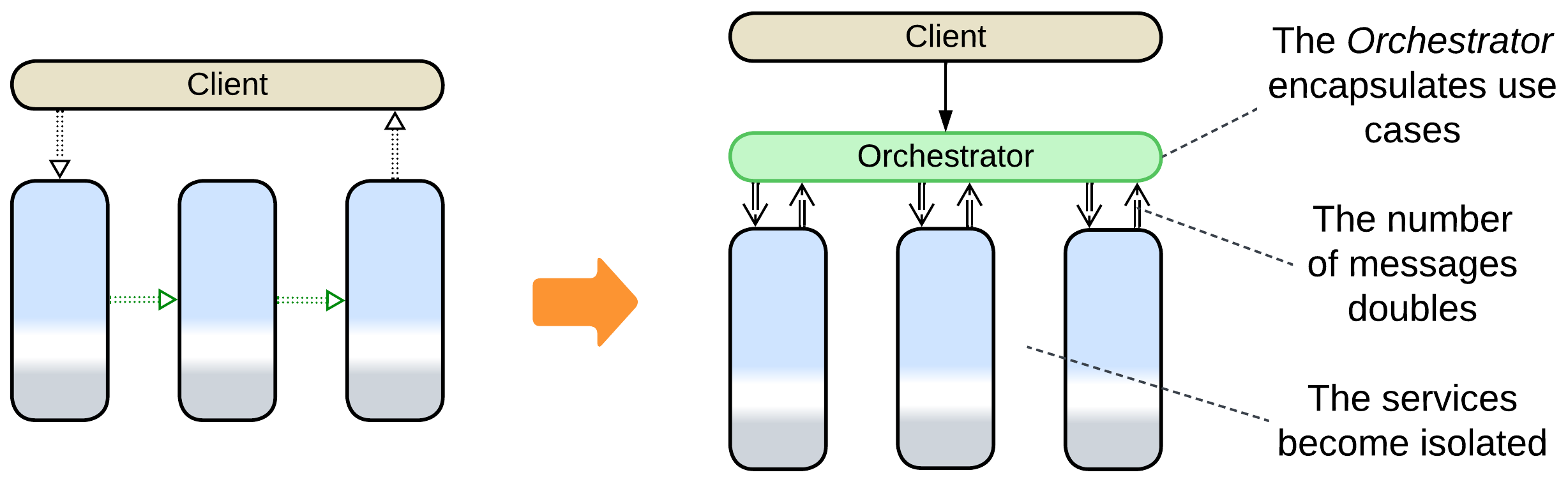
- Adding an Orchestrator turns a Pipeline into normal Services. As the high-level business logic moves into the orchestration layer, the filters don’t need to interact directly, therefore the inter-filter communication channels disappear and the system becomes identical to Orchestrated Services.
Summary #
A Pipeline represents a data processing algorithm as a sequence of steps. It not only subdivides the system’s code into smaller components but is also very flexible: its parts are easy to add, remove, or replace. Multiple use cases can be built over the same set of services. Scalability is good. Event replay helps with debugging. However, its operational complexity restricts the architecture to smaller domains with a limited number of scenarios.