System topologies
In the previous chapter we started with architectural patterns and grouped them in accordance with their structure and function into metapatterns. Now let’s traverse in the opposite direction: from topology (the structure of a system) to the patterns which describe it. We will draw and analyze a map of common system topologies and along the way outline the scope of this book.
Methodology#
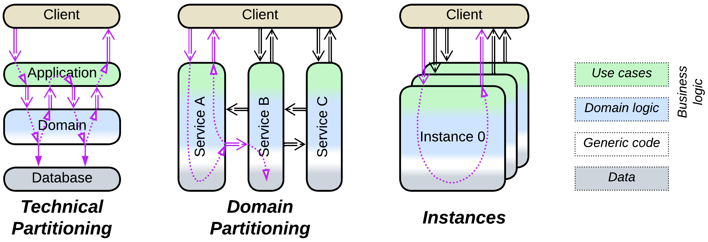
We will rely on our finding that any system has a characteristic representation in the abstractness-subdomain-sharding space. The amounts of a system’s partitioning along each of the three dimensions can be used as its coordinates on a map of system topologies:
- Abstractness corresponds to the technical partitioning [FSA] – subdivision of a system into layers with different roles and technologies. Any use case will likely involve all the layers.
- Subdomain represents the domain partitioning [FSA] – segregation of a system into modules or services that encapsulate distinct parts of the business knowledge. A use case is often localized in one or two subdomains.
- Sharding is about running multiple instances (shards or replicas) of a component.
From theory to practice#
Having a distribution of architectures in a 3D space sounds great, but how do we represent it as human-readable media?
There are at least the following issues:
- Many system topologies feature similar levels of segregation into layers and services, meaning that they belong to the same neighborhood on the map.
- It makes a difference whether a system’s business logic or its infrastructure is subdivided because business logic comprises the bulk of the code. Therefore we cannot estimate a system’s coordinates only from the number of layers or services it contains, which means that we are limited to something like “major layering” and “minor layering” instead of numeric values.
- Sharding of many architectures varies widely and is hard to represent on a flat drawing.
As a result, the following adjustments were necessary to make the map of system topologies comprehensible:
- Sharding is omitted, transforming 3D coordinates into a flat map. Yes, much information is lost, but too much information is no information. Now the map is easier to read.
- I took the liberty of shifting topologies from their real positions to resolve overlaps.
- Even worse, I moved some of the topologies around to group similar architectures.
- Exotic (e.g. Leaf-Spine Architecture) and duplicate (e.g. Microservices) topologies are omitted.
The map of system topologies#
The map contains only basic architectures which are easy to apprehend and name. Any complex system is very likely to be a combination of these simple topologies.
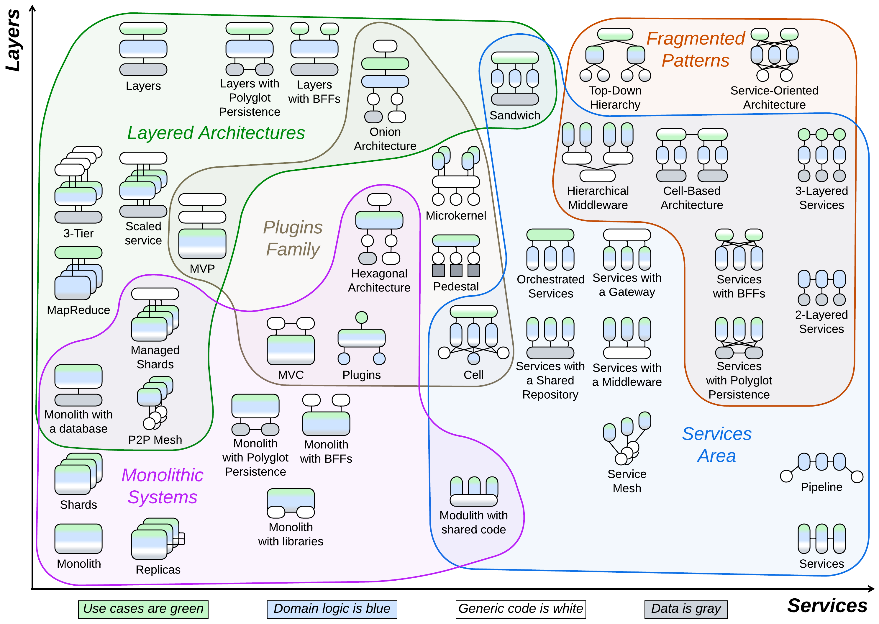
I somewhat arbitrarily divided the map of system topologies into five partially overlapping regions:
- Monolithic, where the bulk of the system is kept in a single component.
- Layered, with mostly technical partitioning and specialized components (drawn in one or two colors which correspond to different kinds of code).
- Services with domain partitioning, meaning that each of the main components includes several kinds of code.
- Fragmented systems built of many smaller parts.
- Plugins that usually have a cohesive core and external modular layers.
This grouping allows us to study the topologies piecemeal without getting lost in their numbers and features.
Monolithic systems#
In the simplest cases a project is too small for any internal structure to be justified – you can code it in a couple of hours without any preliminary design. In other cases the domain is known to be so cohesive that you cannot find good module boundaries – any internal interfaces result in much boilerplate code or degrade performance. Or there is no time left for a thoughtful design!
True Monoliths#
Few system topologies are truly monolithic with one kind of system components:
- Monolith keeps everything together in a single cohesive application which makes sense for small, one-off projects. A long-running Monolith may need to handle inputs and events, for which there are several options:
- Reactor uses a thread for each request and blocks on calls to the OS or other components. This is the simplest server-side implementation.
- Proactor relies on callbacks that all run in a single thread to achieve real-time latency and avoid locks. It is widely used in embedded programming.
- Half-Sync/Half-Async is an internally layered approach that allocates a coroutine or fiber to each task. It is more resource-efficient than Reactor but lacks the real-time responsiveness and flexibility of Proactor.
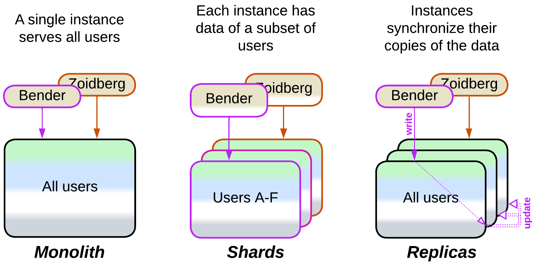
- Shards are multiple instances of a Monolith, each owning a slice of the system’s data. A client must know which shard to access either through storing its address or by querying an Ambassador Proxy library written by the team that deploys the shards. This is the architecture of choice when clients are independent from each other but the entire dataset is too large to fit in a single server.
- Replicas are instances of a Monolith with identical data used to achieve fault tolerance and high throughput. Any writes to one replica must be propagated to the other replicas:
- With semi-specialized replicas all write requests go to a single leader instance which publishes the changes for the other replicas, called followers, to apply to their datasets. Read requests usually go to the followers, and the more read traffic there is, the more followers are deployed.
- If all the replicas are identical, any of them can handle a write request and publish the update for the other replicas to apply. This scales write throughput but involves the chance of data conflicts when the same data record is simultaneously changed on multiple replicas. See Data Grid of Space-Based Architecture.
Monoliths with auxiliary layers#
In other kinds of systems, common in server-side programming, some functionality moves to a dedicated layer while the business logic remains monolithic:
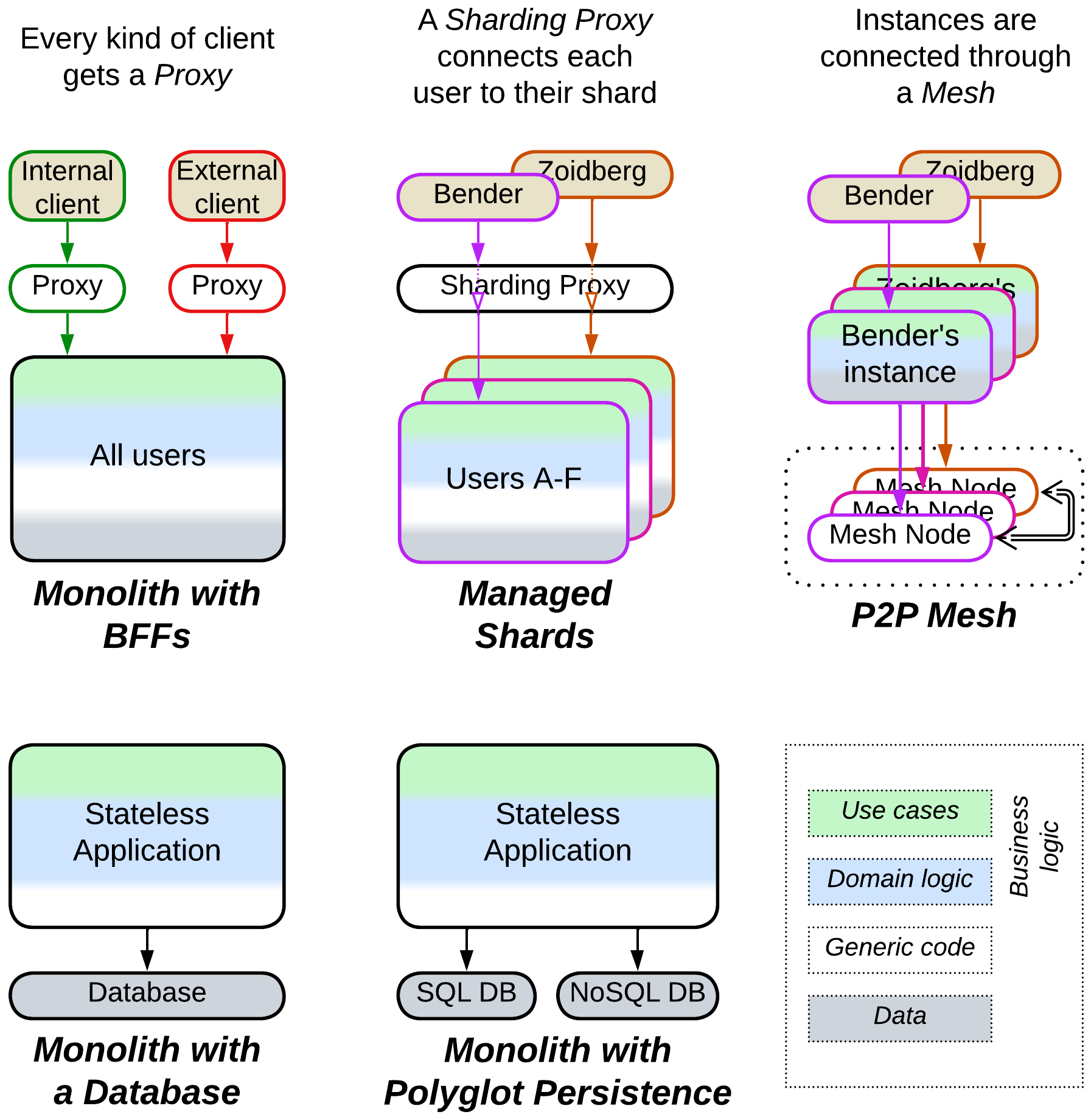
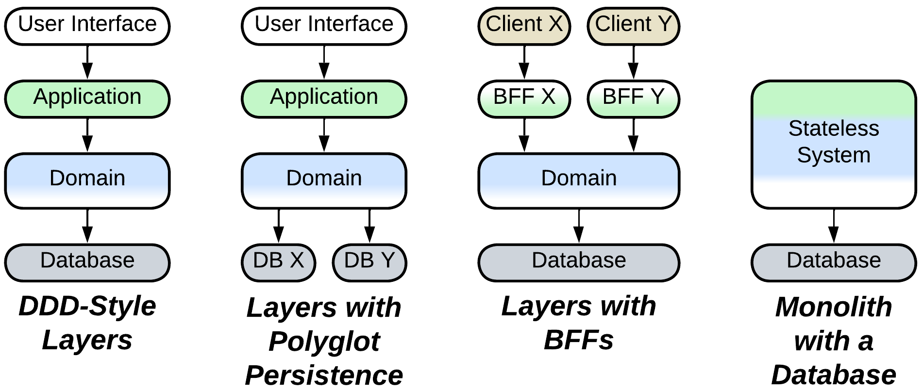
- Monolith with a database relies on an external data storage component for persistence.
- Monolith with Polyglot Persistence uses specialized databases to improve performance.
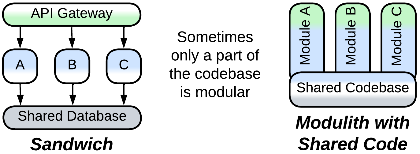
- Monolith with Backends for Frontends employs a Proxy for each kind of client to address variations in the clients’ protocols and security.
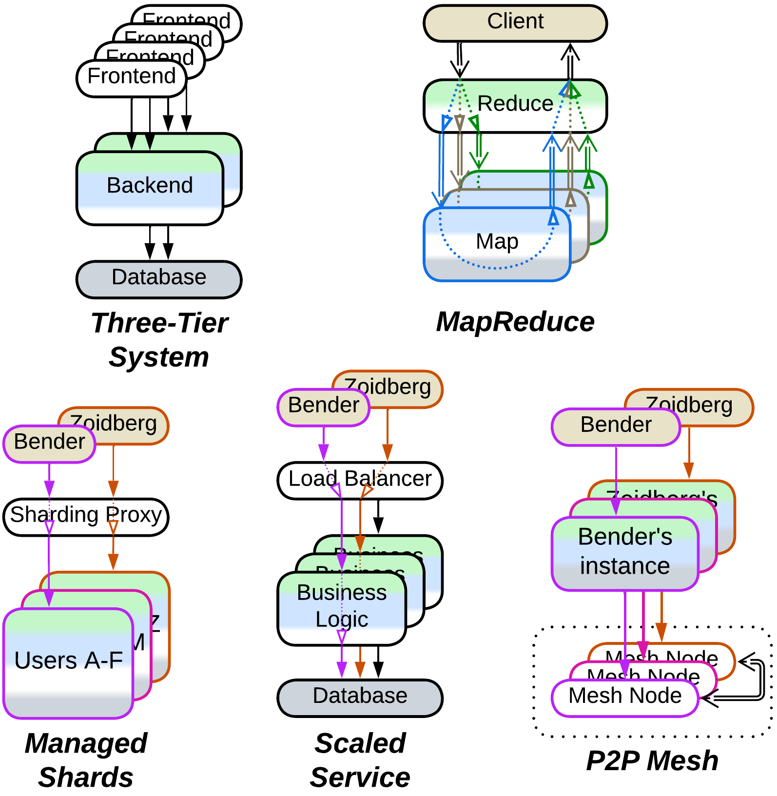
- Managed Shards run behind a single Sharding Proxy which connects each system’s client to the shard that has that client’s data thus isolating the clients from the knowledge of the system’s internal composition.
- Peer-to-Peer Mesh interconnects multiple instances of an application, acting as a distributed Middleware.
Monoliths with Plugins#
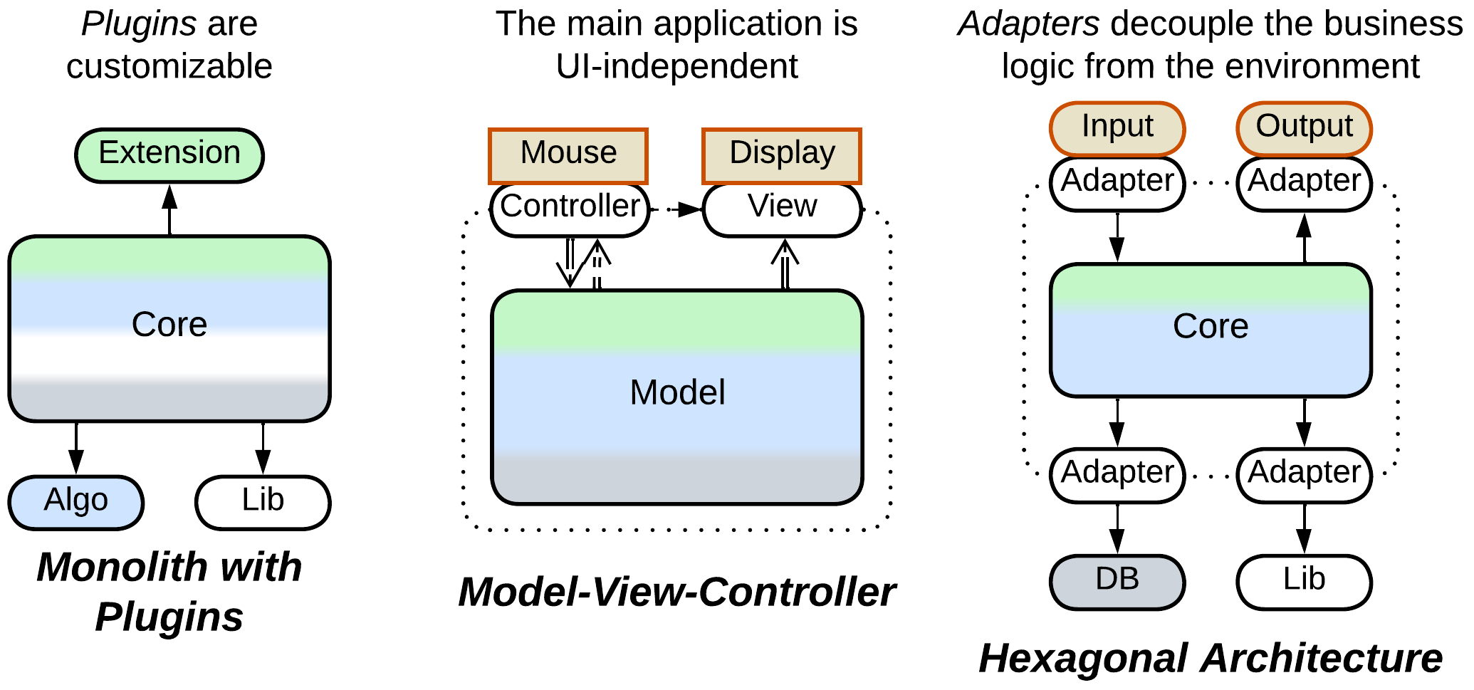
A monolithic core can be extended with disposable additions:
- Plugins allow for parts of the core’s workflow to be supplied by internal or external teams, customizing the experience of the system’s users without modifications to its main code.
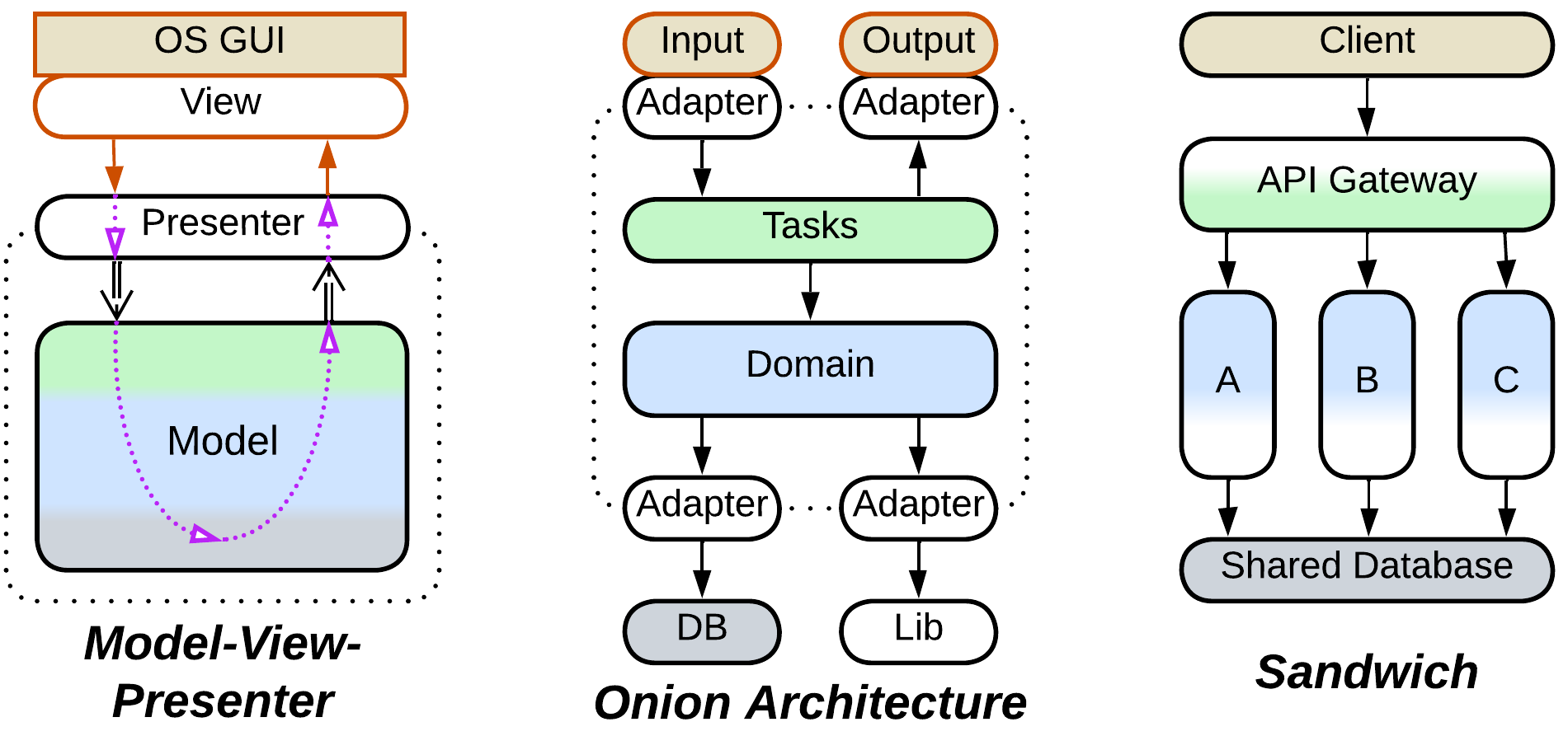
- Model-View-Controller and related patterns provide a presentation layer that isolates the main code from dependencies on the UI framework or network protocol, thus minimizing the effort of porting the software to another platform.
- Hexagonal Architecture keeps the entire business logic self-sufficient by wrapping every dependency with a dedicated Adapter, which not only improves portability but also helps with testing and allows for changing vendors late in the development cycle.
Underdeveloped Moduliths#
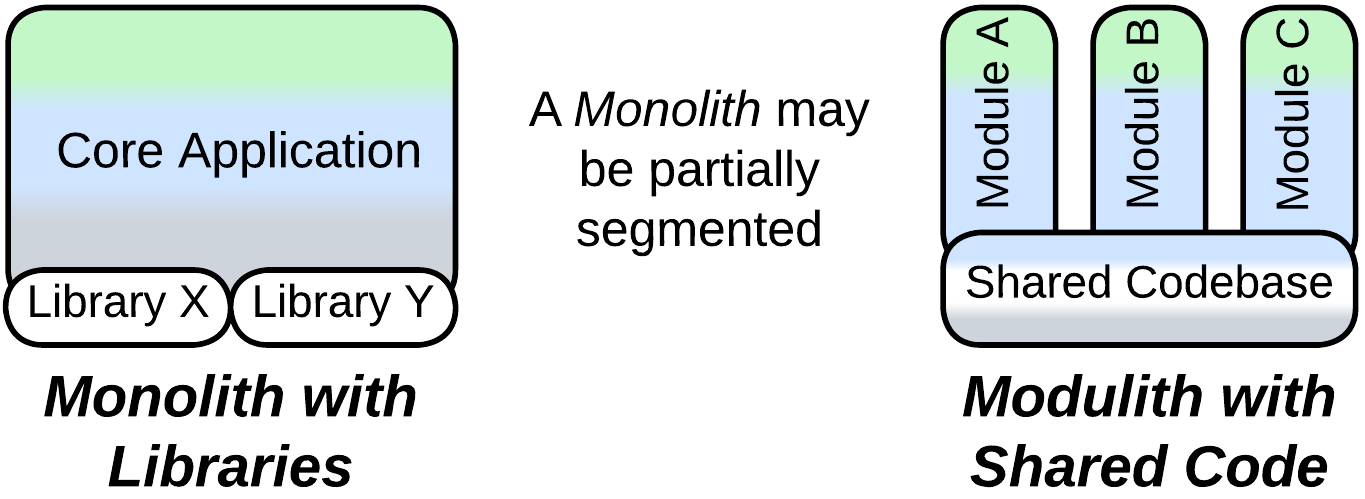
If a Monolith evolves for a long time, it will likely become segmented into subdomain components, yielding a Modulith. As that process is not instantaneous, there are a couple of transitional architectures:
- Monolith with libraries involves subdomain-specific third-party components which are called by its cohesive business logic.
- Modulith with shared code has the business logic largely separated into subdomain modules which still rely on a common codebase for shared functionality.
Layered architectures#
Layering enables the use of specialized technologies and third-party components while avoiding the risky subdivision of business logic. It also allows for parts of the system to differ in their qualities, placement, and scalability. All of that makes layered architectures suitable for full-featured, medium-sized projects run by one or two teams where both the speed of development and supportability matter.
Ordinary Layers#
Typical layered architectures include:
- Layers of various composition, for example:
- Entity-Control-Boundary which represent the domain model, use cases, and interface, respectively. This pattern originated in the age of complex desktop applications.
- Domain-Driven Design decomposition into presentation (interface), application (use cases), domain (business rules), and infrastructure (communication and persistence). It targets enterprise systems.
- Embedded systems with pairs of UI + HMI, SDK + HAL, and FW + HW implemented by distinct parties in the supply chain.
- Layers with Polyglot Persistence where the persistence layer involves multiple databases, usually chosen for their performance with specialized payloads.
- Layers with Backends for Frontends with a dedicated interface and/or application component for each kind of client when the clients differ in their protocols and/or workflows.
- Monolith with a database as a case of rudimentary layering of server-side systems.
Scaled Layers#
Several layered architectures build around scalability:
- Three-Tier Architecture contains a frontend layer with an instance per system’s user, scaled backend, and non-scaled database. It exploits the physical distribution of the system to reap cost, performance, and security benefits.
- Scaled service runs multiple instances of a stateless application between a Load Balancer, which evenly distributes user requests among the instances, and a Shared Database. It is the default approach for scaling a server-side service.
- MapReduce or Scatter-Gather runs a coupled part of a calculation in a non-scaled layer while mutually independent parts are delegated to multiple worker shards.
- Managed Shards rely on a Sharding Proxy layer to connect a client to the appropriate shard. This removes the need for the client to know which shard contains its data.
- Peer-to-Peer Mesh builds a distributed Middleware layer that interconnects instances of a client application.
Other layered systems#
Besides that, there are a few peculiar layered systems:
- Model-View-Presenter family of patterns features layered user interfaces which decouple the main system from a GUI or web framework with the goal of being able to easily switch to another framework version or vendor.
- Onion Architecture or Clean Architecture is a Hexagonal Architecture (see below) with a layered core structured along the ideas of Domain-Driven Design.
- Sandwich architectures are Layers with the domain logic layer split into subdomains. It is a pragmatic low effort approach to tackle complexity in quickly evolving projects that can afford several development teams. It also addresses data-centric domains.
Plugins family#
Some architectures specialize in separating complex core logic from miscellaneous details to make the core independent and reusable under changing conditions. In most cases the core contains monolithic business logic but that may vary among patterns. This family of topologies is prevalent in long-living or highly customizable products whose codebases are too expensive to rewrite to address every trend or fad.
Plugin Architecture#
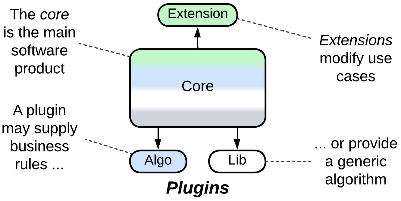
Plugins are external components which supply predefined parts of a host component’s workflow. They may be created by the company that makes the product, often for the sake of selling several flavors with limited or specialized functionality. Or they may come from external programmers, as codecs in video players or customizations for accounting software, to extend the usefulness of a product without overburdening its core codebase.
Separated Presentation#
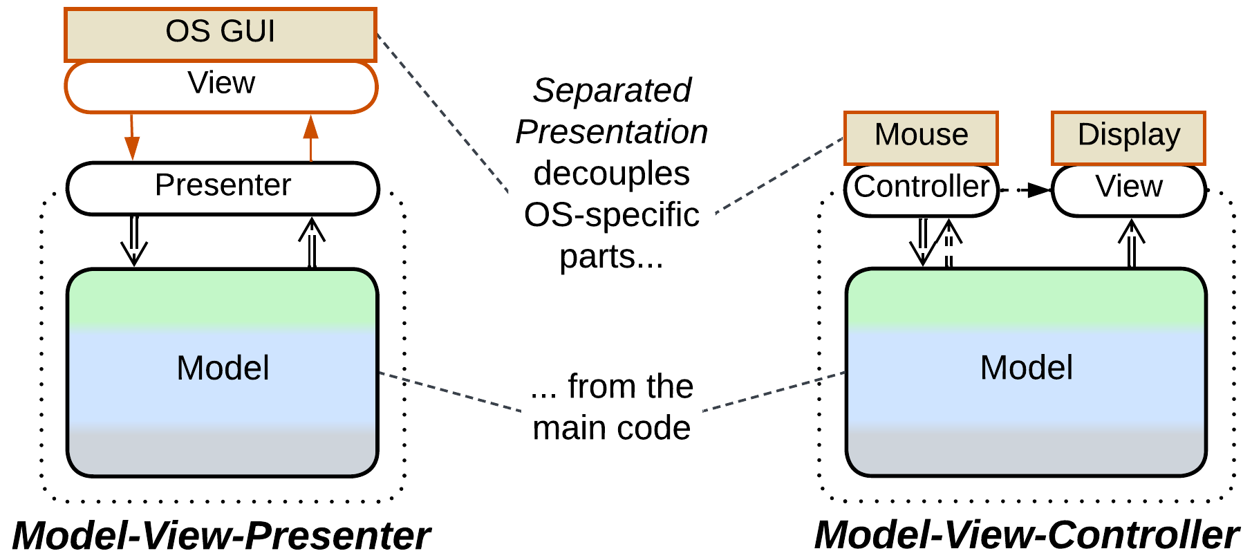
Separated Presentation extracts the user or network interface functionality into a dedicated layer which is often further subdivided. This makes the main codebase reusable in different environments:
- The Model-View-Controller family of patterns has separate modules for platform-specific input and for output which is beneficial when there is no web or GUI framework that can provide a unified high-level user interface.
- The Model-View-Presenter family builds on top of a pre-existing platform-specific presentation layer. Most of these patterns add an intermediate Adapter between the platform-dependent code and the core application.
Control patterns#
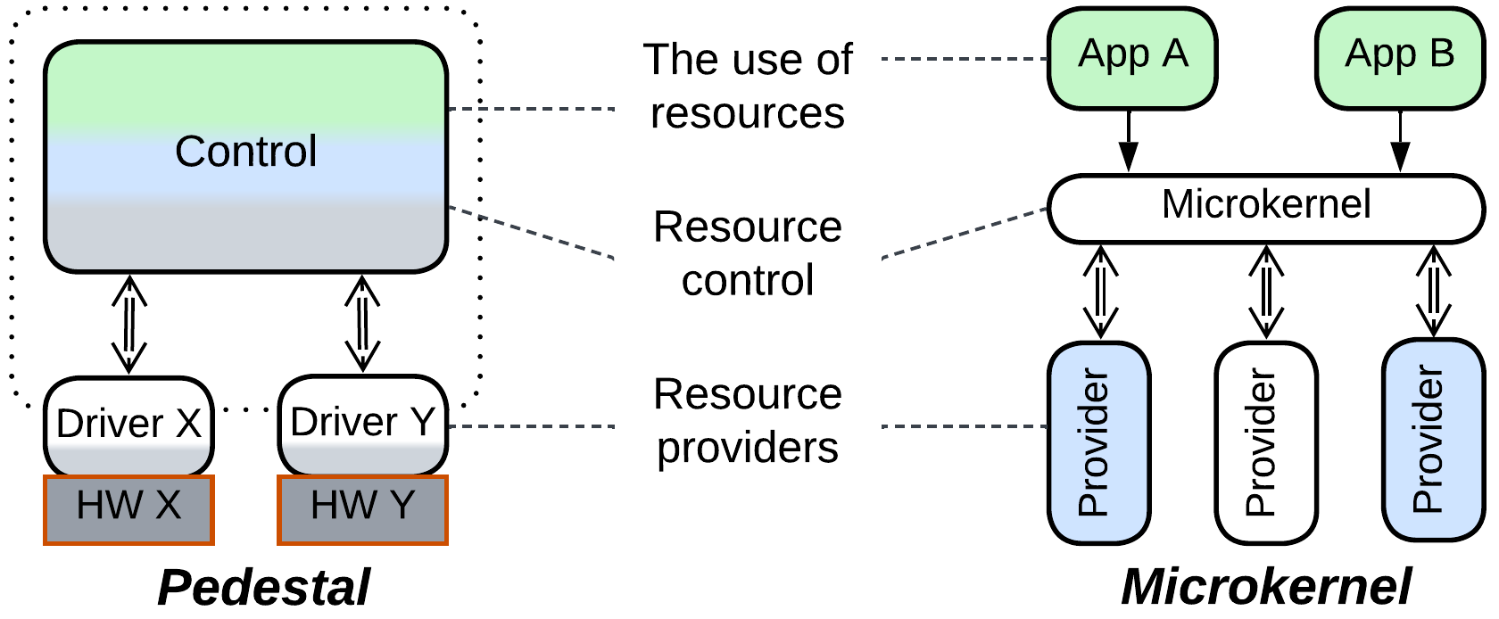
A couple of topologies originate with embedded or systems programming where it is important to abstract the business logic from the hardware components which tend to quickly go out of production and thus need to be replaced with incompatible models:
- Pedestal wraps each hardware component in a system with a dedicated driver to reduce the dependency of the business logic on hardware specifications thus allowing for the software to be reused with different hardware setups.
- Microkernel Architecture relies on an eponymous layer to mediate between resource consumers and resource producers which implement generic interfaces and thus are replaceable. This approach is surprisingly ubiquitous:
- Operating systems are the origin of Microkernel, with user space applications competing for system resources owned by the device drivers.
- Interpreters run user scripts in a sandbox and provide them access to installed libraries.
- Software frameworks follow a similar approach, building a Facade to grant user code a managed access to the framework’s internal components.
- Hypervisors, Virtualizers, and Distributed Runtimes abstract a guest operating system or applications from the platform they run on.
Hexagonal Architecture#
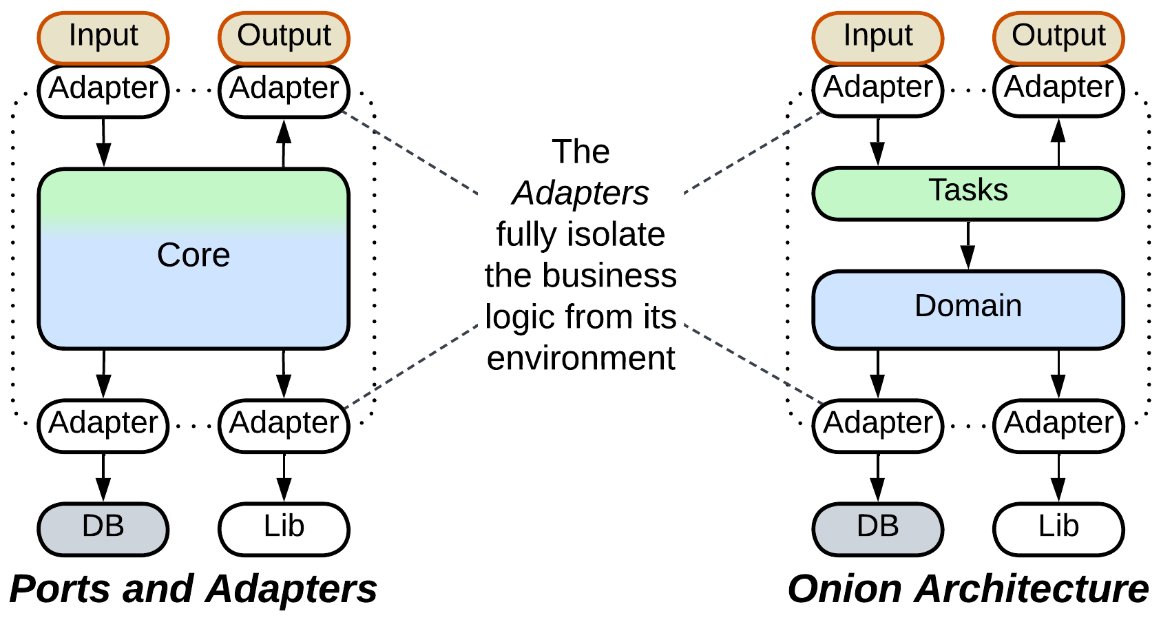
A few architectures fully isolate business logic from its environment, resulting in great portability, simpler automated testing and improved separation of concerns:
- Ports and Adapters (the original Hexagonal Architecture) inserts an Adapter into every communication pathway in or out of its business logic core but does not specify the structure of the core itself, which makes the pattern universally applicable.
- Onion Architecture or Clean Architecture structures the core in accordance with the rules of Domain-Driven Design, limiting the applicability of this topology to enterprise systems or complex backends.
Cell#
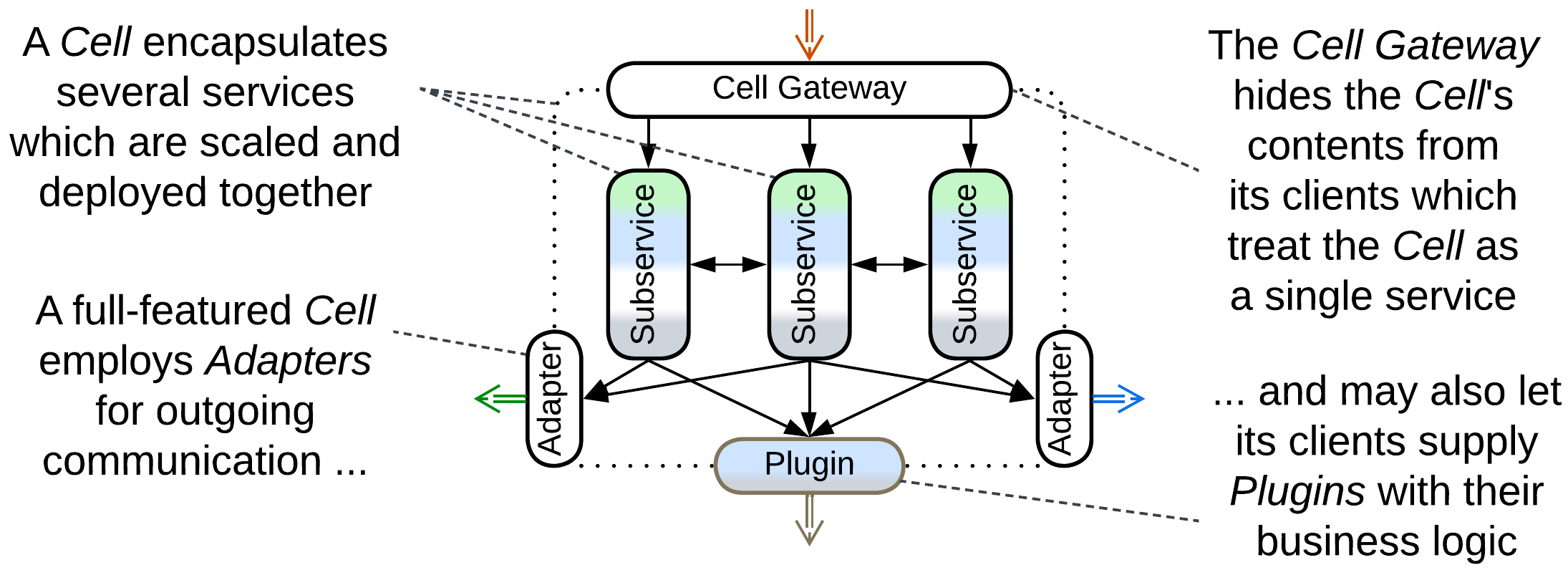
Cell is a building block of huge systems that follow Domain-Oriented Microservice Architecture or Cell-Based Architecture. It is a kind of Hexagonal Architecture with a modular and often distributed core. The internals of a Cell are hidden behind a Cell Gateway which implements the Cell’s public interface. Any outgoing communication, initiated from inside the Cell, goes through its Adapters or through Plugins supplied by peer Cells.
Services area#
Partitioning a system into modules or services which match its subdomains and assigning the components to dedicated teams greatly reduces the cognitive load that the programmers face as each person needs to comprehend only the service they work on. Given that it is cognitive load that determines development speed, most large projects have service-based topologies.
However, full domain partitioning [FSA] is beneficial only when the system’s subdomains are weakly coupled along every level of their functionality, which is why many real-world topologies mix cohesive system-wide layers and decoupled subdomain services.
Barebone services#
A few architectures are completely segmented into subdomains:
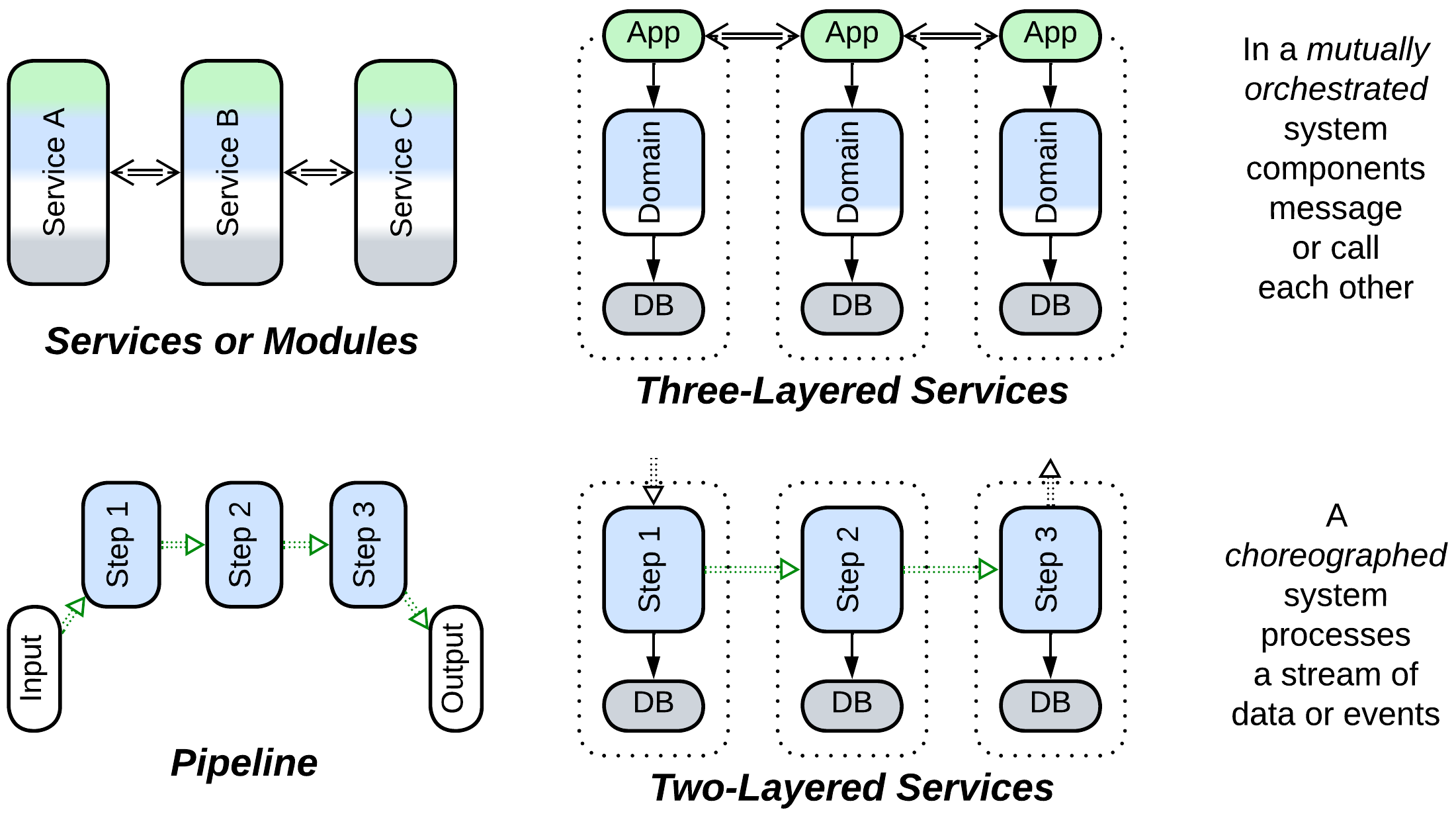
- Distributed Services or in-process Modules rely on mutual orchestration. They come in several kinds:
- Service-Based Architecture tends to employ single instances of services which cover entire subdomains. It is used for multi-team server-side projects with no special performance considerations.
- Modulith (Modular Monolith) runs subdomain-sized components in a single process, sacrificing fault tolerance for consistency and operational costs. This architecture fits smaller Internet businesses.
- Microservices with highly scalable sub-subdomain components implement high load and high budget systems with well-established domain knowledge but frequently changing business needs.
- Actors are asynchronous objects used for real-time tasks that range from embedded telephony to instant messengers to financial systems. Consider them if you benefit from modeling every user of your system as a lightweight independently acting entity.
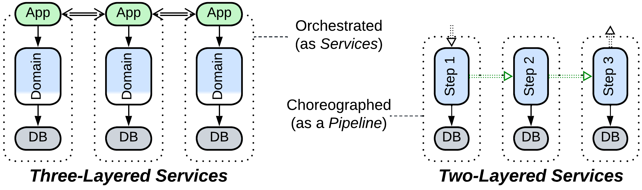
- Three-Layered Services subdivide each service into the use cases, domain logic, and persistence layers, allowing for further specialization of staff and technologies.
- Pipeline is a choreographed system where each component implements a single stage of data or event processing:
- Pipes and Filters is a local and usually linear Pipeline that processes a data stream. It is the architecture of choice for systems with customizable workflows and polymorphic algorithms such as video capture or replay.
- Choreographed Event-Driven Architecture runs multiple branched Pipelines, each implementing a single use case, over a shared set of services. It is an easily extendable alternative to Microservices for domains with a few highly loaded yet simple scenarios.
- Data Mesh collects, transforms, and processes analytical data from a system of services.
- Two-Layered Services split each component of a Pipeline (usually a Choreographed Event-Driven Architecture) into domain logic and persistence layers, emphasizing the use of databases private to their services. Noticeably, the use case logic is present only through the connections between the services.
Services with extensions#
Services become simpler when common aspects are extracted to a dedicated layer:
- Services with a Middleware rely on an external transport and deployment layer which is usually a framework available off-the-shelf:
- Service Mesh is a distributed Middleware for highly scalable systems.
- Message Bus interconnects services that use different communication technologies by translating between their protocols. It is useful in integration of legacy systems.
- Event Mediator drives communication in Event-Driven Architectures.
- Enterprise Service Bus is an orchestrating Middleware that unites several historically separate subsystems into an Enterprise Service-Oriented Architecture.
- Services with a Shared Repository share a data storage or exchange layer and are eligible to implement data-centric domains:
- Shared Database simplifies architectural design and makes data synchronization trivial (see Service-Based Architecture).
- Shared File System is among the simplest methods of organizing Pipelines for processing large volumes of data records.
- Shared Memory is the fastest method of data exchange especially suitable for low latency software.
- Data Grid is a highly scalable, distributed in-memory data store of Space-Based Architecture.
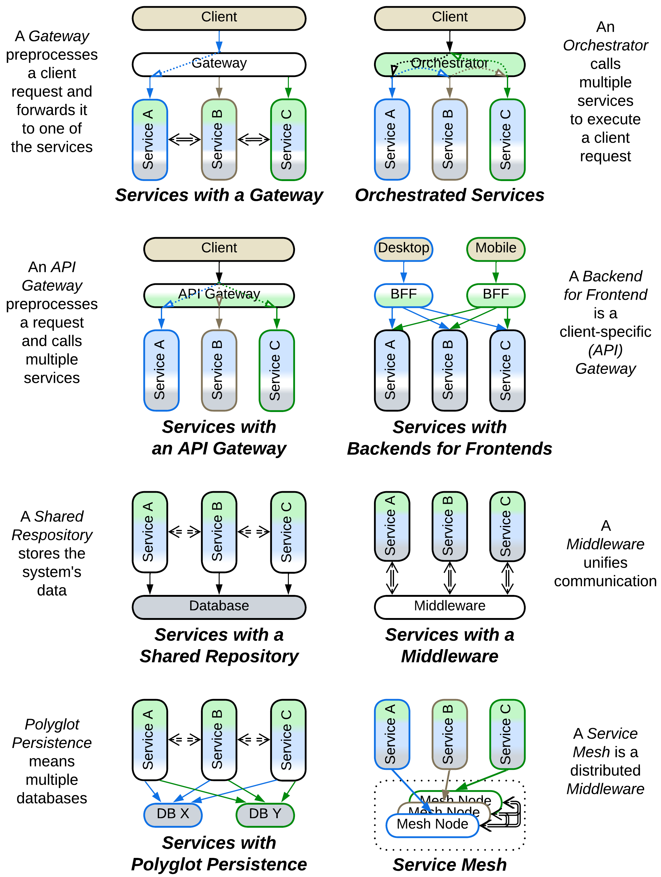
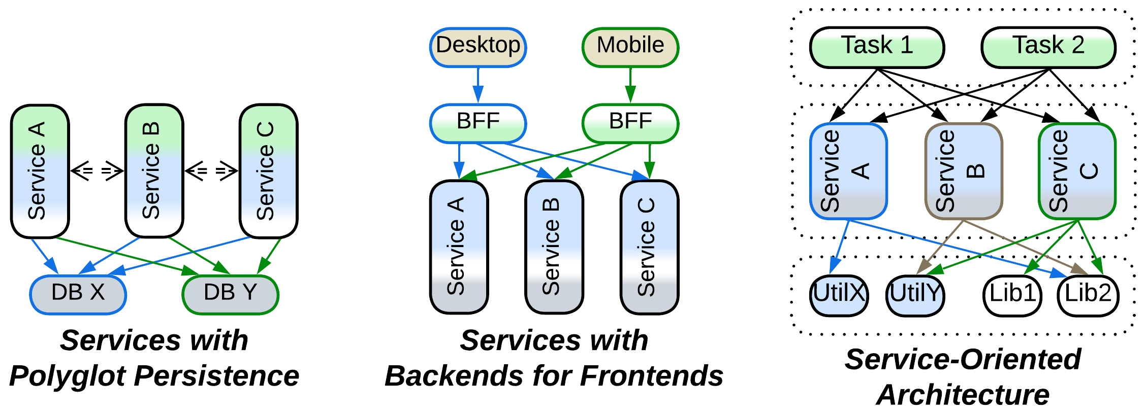
- Services with Polyglot Persistence employ several data stores, usually to improve performance by using each data store in the role it is optimized for.
- Services with a Gateway rely on a shared Proxy layer to handle communication with clients. Third-party Proxies reliably cover security and networking concerns with very little effort from the programmers’ side.
- In Orchestrated Services it is the use cases which are extracted into a system-wide layer. Such subdivision of business logic saves the day when there are many complex system-wide scenarios while the business rules are specific to particular subdomains.
- Services with an API Gateway implement public-API-related tasks – both protocol support and basic orchestration – in a single component which calls underlying services with the domain logic. This is a simplified architecture for ordinary server-side systems.
- Services with Backends for Frontends have a layer of client-specific components that encapsulate clients’ protocols and/or scenarios and are useful when a system serves drastically different kinds of clients.
Hierarchies of services#

Services are building blocks for a couple of hierarchical architectures used in huge projects:
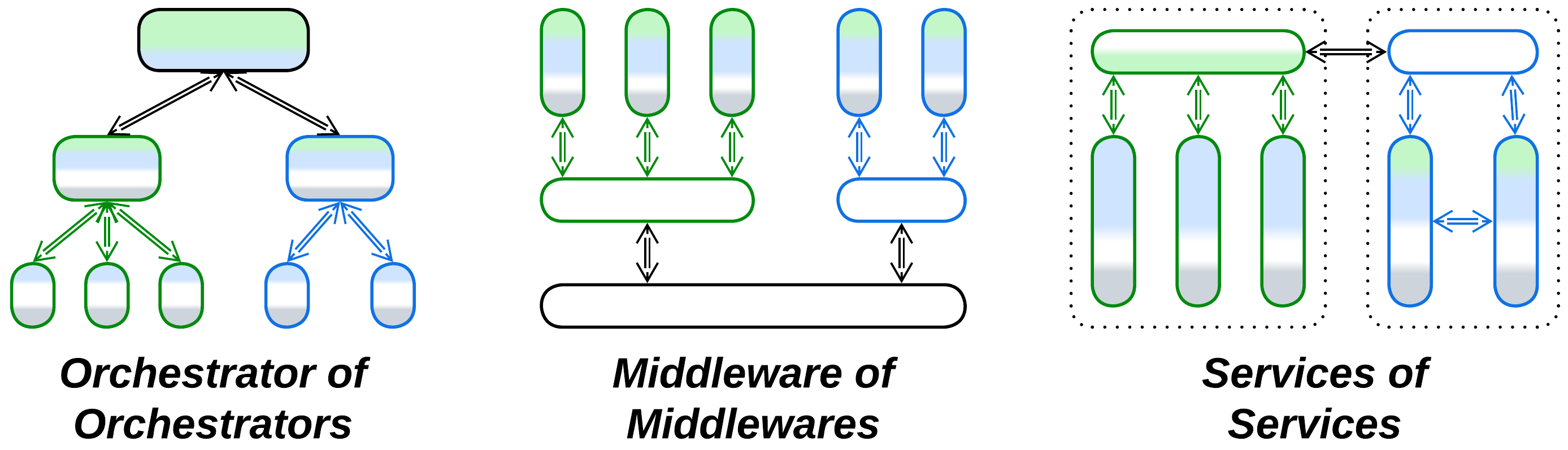
- Cell-Based Architecture is a system of clusters of (often co-deployed) services called Cells. Recursive decomposition lowers the top-level system complexity and decouples the subdomains by making their interdependencies explicit.
- Hierarchical Middleware interconnects several subsystems of services which belong to different organizations or physical networks.
Partially merged services#
There are systems in-between Services and Monolith or Layers:
- In Modulith with shared code the business logic is split into subdomains but still relies on a shared codebase. It is a transitional architecture often seen in growing projects that explore subdomain boundaries.
- In Sandwich only the domain logic layer, which is usually the largest part of the codebase, is segmented into subdomains. This is the most natural subdivision for many real-world systems, which inspires multiple architectures:
- Service-Based Architecture – the pragmatic approach to server-side development – often uses a Shared Database and an API Gateway.
- Space-Based Architecture provides unparalleled elasticity and scalability for data-centric domains with its replicated cache called Data Grid.
- Blackboard Architecture schedules specialized algorithms to solve ill-structured problems.
- Nanoservices are independently scalable functions that run in a cloud and share an (API) Gateway and a database.
Fragmented patterns#
Finally, some architectures are subdivided into both layers of abstraction and subdomains, resulting in topologies containing many small components. This happens when interacting parts of a system vary in their qualities and technologies and thus should stay separate, ordinary decomposition results in components too large for comfortable development, or both.
Layers of services#
A few topologies are made of layers, each of which is subdivided into services:
- In Services with Polyglot Persistence there are several specialized data stores with shared access. This topology may emerge from a performance optimization of Services with a Shared Repository.
- Services with Backends for Frontends employ a dedicated Proxy, Orchestrator, or API Gateway for each kind of client. This makes sense when the system’s clients have very little in common.
- Service-Oriented Architecture features fragmented application, domain, and utility layers, with each component of a higher level calling multiple components from a layer below it. It enables code reuse, for better or worse, and has reasonably small services even in huge projects but suffers from slow development caused by extensive interdependencies between teams.
Layered services#
More often than not, services are layered internally:
- Orchestrated Three-Layered Services distinguish between the application (use cases), domain (business rules), and persistence (database) layers.
- Choreographed Two-Layered Services contain only the domain and persistence layers because the application logic resides in the graph of connections between the services.
Hierarchies#
Finally, there are hierarchical topologies with recursive partitioning:
- Top-Down Hierarchy is arguably the best way to implement a system that involves many kinds of somewhat related entities. It emerges in domains as diverse as compilers, industrial automation, graphical user interfaces, and online marketplaces.
- Hierarchical Middleware interconnects subsystems that differ in their communication protocols.
- Cell-Based Architecture splits every large subdomain service into a group of subservices encapsulated with a Cell Gateway. This keeps individual services small without spreading hundreds of them into the system level.
Common motifs#
Every area of the topologies map highlights certain design principles:
- Small and simple systems may stay cohesive as Monoliths or Shards.
- Medium-sized software benefits from functional partitioning [FSA] into Layers.
- Long-lived projects become stabilized by extracting any volatile code into expendable modules. Different applications of this principle yield Plugins, Hexagonal Architecture, and Microkernel.
- Large software is decomposed into subdomains owned by dedicated teams. See Services and Pipeline.
- Huge systems require recursive decomposition as found in Service-Oriented Architecture and Hierarchy.
Other motifs are harder to notice as they apply to both scaled layered systems and those subdivided into services:
- There is often a managing layer that makes use of underlying components:
- A Proxy is an interface that receives and pre-processes client input, then forwards the resulting request to whatever is behind it.
- An Orchestrator is an application that implements complex use cases which turn a single event or client request into a chain of calls to the lower layer.
- Backends for Frontends segment a managing layer into client-specific services.
- A platform layer provides some functionality to other system components:
- A Middleware deploys and interconnects Services or Replicas.
- A Shared Repository stores the system’s data, offering consistency and persistence.
- Polyglot Persistence subdivides a Shared Repository layer.
- Sandwich wraps Services or Replicas with both managing and platform layers.
- A Mesh interconnects any components that use it.
As we see, metapatterns emerge as archetypes shared among system topologies.
Summary#
There are many system topologies with various degrees of segregation into layers and subdomains. No single architecture is a silver bullet, each topology has its use depending on the circumstances. The following chapters of this book explore archetypes shared among topologies which are called metapatterns.